Why Choose a Pressure Control Valve for Your System?
A pressure control valve helps keep a system within its intended operating range when supply pressure shifts or demand changes. In a water line, that may mean preventing a sudden surge from stressing fittings. In a process line, it can mean protecting sensitive equipment from pressure swings. The result is steadier operation, not magic. The valve must match the fluid, pressure range, flow rate, and system layout.
A practical design reminder, inspired by process-control expert David W. Spitzer’s focus on measurement and control, is: “Control begins with knowing what pressure is doing.” This is an editorial summary, not a verified quotation. That distinction matters. Good selection starts with real operating data, including normal and peak pressures, rather than a guess based on pipe size alone. A pressure control valve that is poorly sized may hunt, restrict flow, or fail to hold the target pressure. Small details count.
This article explores how these valves work, where they fit, and what to check before choosing one. It also considers materials, maintenance, and common sizing mistakes. The best choice depends on the whole system. And sometimes, the available data are incomplete. That deserves a closer look—not a confident assumption.
What Is a Pressure Control Valve?
Why Choose a Pressure Control Valve for Your System?
What Is a Pressure Control Valve?
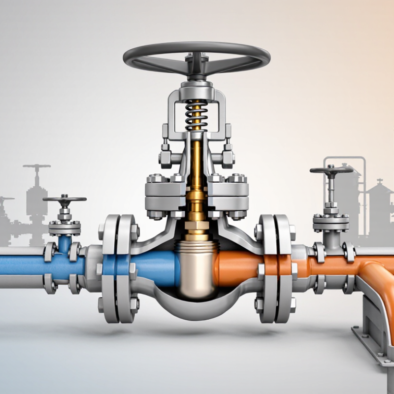
A pressure control valve is a mechanical device that regulates fluid pressure inside a piping system. It responds to pressure changes and adjusts its opening to maintain a safer, more stable operating range. Many designs use a spring, diaphragm, piston, or pilot system to sense pressure and control flow.
Pressure changes quickly. That detail matters.
For example, a pressure-reducing valve lowers excessive inlet pressure before fluid reaches sensitive equipment. A back-pressure valve maintains pressure upstream, while a relief valve opens when pressure exceeds a defined limit. These functions are different, even though the valves may look similar from outside.
Technicians usually examine inlet pressure, outlet pressure, flow rate, fluid type, temperature, and pipe size before selecting a valve. I have seen systems struggle because the valve matched the pipe diameter but not the actual flow conditions. Bigger is not always better. An oversized valve may hunt, create noise, or respond poorly at low flow.
Material compatibility also deserves careful attention, especially with corrosive, abrasive, or high-temperature fluids. The valve should include suitable pressure ratings and a practical maintenance plan. Operators need clear adjustment ranges and reliable access for inspection. Some installations also require fail-open or fail-closed behavior during power or signal loss.
A pressure control valve is not a complete safety strategy. It works best with correctly set instruments, documented testing, and trained personnel. Small errors in calibration can produce large pressure changes. Rechecking the real operating data may reveal that the original selection needs improvement.
What Types of Pressure Control Valves Are Available?
Why Choose a Pressure Control Valve for Your System?
What Types of Pressure Control Valves Are Available?
Pressure control valves help keep hydraulic or pneumatic systems within intended pressure limits. The right type can protect components, support steady movement, and reduce unwanted pressure changes. Different valves solve different problems. They are not interchangeable.
A pressure-reducing valve maintains a lower pressure in a branch circuit, such as one feeding a small actuator. A pressure-relief valve opens when pressure exceeds its set point, directing excess flow away to help prevent damage. Sequence valves allow operations to happen in order by opening after a set pressure is reached. Counterbalance valves help control loads that might otherwise drop too quickly, while unloading valves divert pump flow when it is not needed at full pressure. That matters. Selection depends on circuit layout, flow rate, load behavior, and operating pressure. A valve that looks suitable on paper may behave differently when the system warms up or the load changes.
Tips: Check the valve’s pressure and flow ratings against actual operating conditions. Leave room for adjustment, and verify settings with a suitable gauge. Small details can matter. A neat specification is useful, but it does not replace testing the assembled system.
What Benefits Do Pressure Control Valves Provide?
Pressure control valves provide more than basic flow restriction. They keep downstream pressure near a defined setpoint, even when demand changes sharply. In a processing line, that can mean steadier actuator movement, fewer pressure shocks, and more consistent product quality. A properly sized valve also helps protect pumps, filters, gauges, and seals from avoidable stress.
Energy performance matters too. The International Energy Agency reports that industry uses about 37% of global final energy, making small efficiency gains commercially important. For compressed-air systems, the U.S. Department of Energy’s Improving Compressed Air System Performance sourcebook notes that reducing discharge pressure by roughly 2 psi may cut energy use by about 1%, when the system can operate safely at the lower setting. The result depends on leaks, piping, and demand patterns. No valve works miracles.
In field commissioning, I have seen operators set pressure higher “for safety,” only to increase leakage and component wear. A control valve can correct that habit by maintaining pressure where the process needs it, not where fear places it. Relief protection remains essential, and sizing must reflect flow range, temperature, fluid behavior, and failure position. Poor sizing causes hunting, noise, or unstable control. That part is often underestimated. Regular inspection and calibration also matter, because a drifting sensor can make a reliable valve appear unreliable.
Why Choose a Pressure Control Valve for Your System? - What Benefits Do Pressure Control Valves Provide?
| Valve Function |
How It Controls Pressure |
Key System Benefit |
Common Applications |
Selection Consideration |
| Pressure-reducing valve |
Reduces a higher inlet pressure to a lower, controlled downstream pressure. |
Helps protect downstream equipment and maintain a suitable operating pressure. |
Water distribution, compressed-air systems, and hydraulic circuits. |
Confirm the required outlet pressure, flow range, and inlet-pressure conditions. |
| Pressure-relief valve |
Opens when pressure reaches its set point, allowing fluid to discharge or return to a lower-pressure part of the system. |
Helps limit excessive pressure and reduce the risk of damage to components. |
Hydraulic power units, pumps, and pressurized process systems. |
Set pressure and discharge capacity must suit the system design; relief valves do not replace other required safeguards. |
| Back-pressure valve |
Restricts flow to maintain a minimum pressure upstream of the valve. |
Supports stable upstream pressure where a process or component needs a minimum pressure. |
Metering systems, process lines, and pump discharge arrangements. |
Check fluid compatibility, required back pressure, and the valve’s flow characteristics. |
| Pressure-sequence valve |
Opens a secondary flow path after the primary circuit reaches a preset pressure. |
Enables pressure-dependent sequencing of operations in a hydraulic circuit. |
Hydraulic machinery with multiple actuators or staged operations. |
Set the opening pressure to match the intended operating sequence and circuit requirements. |
| Unloading valve |
Diverts pump flow to a low-pressure path when a specified pressure or operating condition is reached. |
Can reduce unnecessary pressure loading and heat generation during suitable operating cycles. |
Hydraulic systems with accumulators or intermittent demand. |
Verify pump flow, unloading pressure, and the system’s return-line capacity. |
| Differential-pressure control valve |
Regulates the pressure difference across a component or section of a system. |
Helps maintain more consistent conditions across equipment as system conditions change. |
Heating and cooling circuits, filtration systems, and process equipment. |
Specify the target differential pressure and check the operating flow range. |