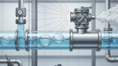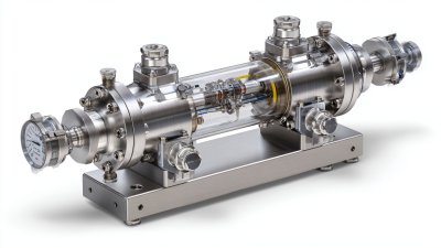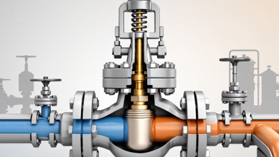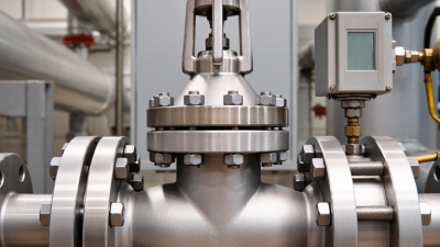
Choosing a pneumatic check valve in 2026 is no longer a simple catalog exercise. Global buyers must match airflow, pressure, temperature, installation position, and maintenance access. A small valve beside a robotic gripper may face rapid cycling, oil mist, and sharp pressure changes. A larger unit on a compressed-air header may need low cracking pressure and quiet closing. The details matter.
Pneumatic check valve designs include spring-loaded, swing, shuttle, pilot-assisted, and inline models. Each type responds differently to backflow, contamination, vibration, and limited space. Valve engineer David W. Spitzer offers a useful practical principle: “Valve selection must begin with the process, not the catalog.” That warning remains relevant, even when product data looks impressive. Buyers should verify flow coefficients, sealing materials, port standards, pressure ratings, and test documentation. Marketing language alone is not enough.
This guide examines the top pneumatic check valve types for global buyers in 2026. It considers factory automation, medical equipment, packaging lines, air preparation systems, and mobile machinery. Real operating conditions often expose weaknesses that laboratory sheets hide. A valve may perform well during a clean bench test, then chatter in a dusty production area. That possibility deserves attention. Buyers should also question assumptions about universal compatibility, delivery reliability, and service support. No single design wins everywhere. The better choice is the one that protects equipment, stabilizes airflow, and remains understandable to the maintenance team. Small oversights can become expensive failures.
ISO 5598 provides standardized terminology for fluid power systems and components, helping buyers describe pneumatic check valves consistently. In plain terms, a check valve permits airflow in one direction and restricts reverse flow. It does not control direction like a directional valve. A pressure difference moves its internal element, such as a ball, poppet, or disc, away from the seat. Reverse pressure pushes the element back. Simple action.
Common designs include spring-loaded poppet valves, ball valves, and compact in-line units. Their behavior depends on details, not just the name. Spring force affects opening pressure, while the passage and seat influence flow and leakage. A valve may look suitable on a drawing yet cause a pressure drop in a small cylinder circuit. That is easy to overlook.
For selection, compare connection size, rated flow, working pressure, media compatibility, and installation direction. Check the specified cracking pressure: a valve that opens too late can slow an actuator. A valve that seals poorly may allow a cylinder to drift during a pause. Keep dust and seal fragments away from the seat; even a tiny particle can matter. Test the assembled circuit under realistic pressure and load. Catalog data helps, but it cannot replace that check.
2026 Top Pneumatic Check Valve Types for Global Buyers
Inline check valves suit compact air circuits with straight tubing and limited installation space. Their simple flow path reduces turbulence and usually supports quick maintenance. They work well near cylinders, filters, and directional control valves. However, incorrect port sizing can cause noticeable pressure loss during rapid cycling.
Angle check valves turn airflow by 90 degrees, helping installers route tubing around crowded machine frames. They are practical in tight cabinets and modular pneumatic panels. The bend may increase resistance, especially when the valve is undersized. Buyers should compare cracking pressure, flow rate, port thread, and sealing material before ordering.
Shuttle valves allow either of two inlet signals to operate one outlet. This suits dual-control circuits, safety-related logic, and independent pneumatic commands. They can simplify layouts, but trapped pressure may confuse troubleshooting.
Pilot-operated check valves provide stronger load holding and controlled release, which benefits vertical cylinders and clamping systems. They need correct pilot pressure, clean air, and careful exhaust design. A low pilot signal may leave the actuator partially locked. That detail is easy to miss.
Selection should follow the circuit’s real behavior, not only a catalog diagram. Review pressure fluctuations, temperature, mounting direction, cycle frequency, and maintenance access. Request test data and traceable material information from suppliers. A valve that performs well on a bench may respond differently beside a vibrating compressor. Engineers sometimes choose the smallest acceptable model to save space. That choice can reduce flow stability. Rechecking the complete circuit is worth the extra time.
Choosing a pneumatic check valve starts with the required airflow, not the port size alone. Spring-loaded in-line valves suit compact installations, while lift or swing designs may fit other flow paths. Check the valve’s rated Cv against the system’s peak demand and the manufacturer’s flow data. Cv alone is not enough for compressed air; pressure, temperature, and whether values are stated as standard or actual flow also matter. Small details count.
A valve with a cracking pressure of 0.1–0.5 bar needs that upstream-to-downstream pressure difference to begin opening. That is not the same as its pressure drop at full flow. Compare the pressure-drop curve at the actual operating airflow, then confirm adequate pressure remains at downstream equipment. A valve near the top of this cracking range may restrict a low-pressure circuit. Keep units consistent.
In commissioning, measure pressure on both sides while the actuator is moving; static readings can hide a flow problem. A tidy spreadsheet can still mislead if it uses average demand instead of a short airflow peak. Leave sensible margin, but avoid oversized valves that add bulk without solving the real restriction. Recheck the selection if tubing length or fittings change.
Seal Materials Compared: NBR, FKM, and EPDM Across -40°C to 200°C
Seal choice affects leakage, cracking pressure, and service life in a pneumatic check valve. NBR is a practical option for general compressed air, especially where oil mist may be present. Many standard grades work around -30°C to 100°C, but exact limits vary. A hardened lip or flattened O-ring can let air pass backward. Small details matter.
FKM suits higher temperatures and many oils and chemicals. Some grades can operate near 200°C, though prolonged heat may still shorten seal life. Standard FKM grades can become stiff in deep cold; specialized low-temperature compounds may reach lower limits. Check the supplier’s grade data, not just the material name.
EPDM often performs well in cold conditions, with some grades rated near -40°C, and resists water and steam. It is generally a poor match for petroleum oils.
No single elastomer reliably covers -40°C to 200°C. Real conditions count. Consider air temperature, pressure cycles, condensate, lubricant, and how often the valve opens. A valve tested with dry air may behave differently when cold, wet air chills its seal. Leave a margin beyond the expected temperature range, and verify compatibility with the actual fluid and duty cycle before selection. Even careful choices need checking in service.
ISO 4414 sets safety requirements for pneumatic systems, including pressure isolation, stored-energy release, and protection against unexpected movement. For a check valve, buyers should verify its flow direction, cracking pressure, leakage limits, and behavior after air loss. Test the actual assembly, not just the valve on a clean bench. Details matter. A useful checklist can still miss hurried maintenance or a poorly placed exhaust port.
CE marking is not a universal quality certificate. In 2026, confirm which EU rules apply to the product and its intended assembly; machinery obligations remain under Directive 2006/42/EC until the new Machinery Regulation applies in 2027. Keep the risk assessment, technical file, and declaration consistent with the product supplied. The U.S. Department of Energy’s Improving Compressed Air System Performance guide reports that leaks can waste 20–30% of compressor output. That makes leak-tight shutoff and accessible inspection practical purchasing criteria, not minor details. Not always. Request pressure, temperature, media, and cycle-life test conditions, then compare them with the real installation. These figures cannot predict every plant’s losses.
| Valve Type | Operating Principle | Typical Uses | Key Selection Checks | Compliance and Documentation Considerations |
|---|---|---|---|---|
| Inline non-return (check) valve | Allows flow in one direction and blocks reverse flow. A spring-loaded design may require a specified cracking pressure before opening. | Preventing reverse flow in supply lines, protecting components, and isolating branches in pneumatic circuits. | Confirm flow direction, port size and thread standard, rated pressure, cracking pressure, flow capacity, air quality requirements, and seal compatibility. | For system-level safety, assess the valve within the circuit under ISO 4414. Request material, pressure-rating, and test documentation appropriate to the application. |
| Pilot-operated check valve | Blocks reverse flow until a pilot signal applies pressure to release the closure element. The required pilot pressure depends on the valve design and circuit pressures. | Holding an actuator position or preventing unintended movement when the control signal is removed, where the circuit design permits. | Check pilot ratio and pressure limits, leakage characteristics, release behavior, installation orientation, and whether additional load-holding safeguards are needed. | Do not treat the valve alone as a personnel-safety device or as a guarantee against actuator drift. Validate the complete circuit and risk controls against applicable requirements, including ISO 4414. |
| Shuttle valve (pneumatic OR valve) | Connects one of two inlet signals to a common outlet while the internal element separates the inlets from one another. | Selecting between two pneumatic command signals or supplying an output from either of two sources. | Verify port identification, flow capacity, pressure range, signal compatibility, and the risk of unwanted signal interaction in the circuit. | Confirm that the selected arrangement meets the system’s safety and functional requirements. Document the circuit logic and operating conditions as part of the system assessment. |
| Quick-exhaust valve | Provides a low-restriction exhaust path near an actuator, allowing air to exhaust locally rather than returning through the directional control valve. | Reducing exhaust-path restriction in pneumatic actuator circuits when the design calls for faster venting. | Check port arrangement, exhaust flow capacity, silencer compatibility, noise, contamination protection, and the effects of faster actuator movement. | Assess exhaust direction, noise, and the machine’s resulting motion as part of the risk assessment. A quick-exhaust valve is not, by itself, an energy-isolation device. |
| Compact or cartridge check valve | Provides one-way flow control in a compact body or cavity-mounted format; construction and serviceability vary by design. | Manifolds, space-constrained assemblies, and integrated pneumatic equipment. | Confirm cavity or manifold interface, sealing method, replacement procedure, flow direction, pressure rating, and availability of compatible service parts. | Check that the valve is installed in an assembly designed for its interface and pressure limits. Keep traceable technical documentation for the completed pneumatic system. |
| Global Buyer and Compliance Checks for 2026 | ||||
| ISO 4414 | ISO 4414:2010 covers general rules and safety requirements for pneumatic fluid power systems and their components. It is a system and component safety standard; it is not, by itself, a product certification or a blanket approval for an individual valve. | |||
| CE marking in the EU | CE marking is required only when the product falls within the scope of applicable EU legislation that requires it. A pneumatic valve supplied as a component is not automatically required to carry CE marking under machinery legislation. Determine the product’s legal classification and applicable legislation before requesting or applying a CE mark. | |||
| EU machinery rules in 2026 | In 2026, Machinery Directive 2006/42/EC remains the principal EU machinery legislation. Regulation (EU) 2023/1230 generally applies from 20 January 2027. Buyers should confirm the applicable rules for the product and date of placing on the EU market. | |||
| Pressure equipment assessment | The Pressure Equipment Directive (PED) generally concerns pressure equipment with a maximum allowable pressure greater than 0.5 bar, but whether a particular valve is in scope and what conformity route applies depends on its classification, intended use, and applicable exclusions. Request the supplier’s documented assessment rather than assuming every pneumatic valve needs PED CE marking. | |||
| Buyer documentation | Request a datasheet with pressure and temperature limits, flow or cracking-pressure data where relevant, port and thread details, materials and seal information, installation instructions, traceability details, and any declarations or test records required for the destination market and application. | |||
| Application validation | Check operating pressure, air quality, flow demand, ambient conditions, expected cycle life, leakage requirements, maintenance access, and the consequences of valve failure. Validate the complete circuit and machine; component selection alone does not establish system compliance. | |||
| Important: Standards, legislation, and conformity obligations depend on the product classification, intended use, system design, and destination market. Confirm current requirements with qualified compliance personnel or the relevant authority before placing equipment on the market. | ||||