What Is a Flow Check Valve and How Does It Work?

A flow check valve is a small component with a serious responsibility. It allows fluid to move forward and blocks unwanted reverse flow. In piping systems, that simple action can protect pumps, compressors, filters, and storage tanks from damage.

Greg Johnson, a valve-industry educator and author, explains, “A check valve is designed to allow flow in one direction and prevent flow in the other.” The principle sounds straightforward. Real systems are less tidy. A flow check valve responds to pressure differences, not human commands. When inlet pressure rises, the disc, ball, piston, or swing mechanism opens. When pressure falls or reverses, the closing element returns to its seat. That movement may happen in seconds.

The details matter. An incorrectly sized valve can create excessive pressure loss. A weak spring may allow reverse leakage. A fast-closing design may produce water hammer, causing sharp knocking inside the pipe. Installation direction also matters. The arrow on the body should match the intended flow path. It is easy to overlook.

Not every check valve suits every service. Clean water, wastewater, steam, oil, and corrosive chemicals require different materials and designs. Engineers should review flow rate, pressure, temperature, viscosity, pipe position, and cracking pressure before selection. Manufacturer data remains essential.

This guide examines how a flow check valve works, where it is used, and why failures occur. It also considers maintenance and practical installation limits. The explanation cannot cover every unusual system. That is worth remembering. Field conditions often challenge textbook assumptions.
What Is a Flow Check Valve and How Does It Work?

Definition and Purpose of a Flow Check Valve

What Is a Flow Check Valve and How Does It Work?

Definition and Purpose of a Flow Check Valve

A flow check valve is a mechanical device that permits fluid to move in one direction. It automatically restricts reverse flow when pressure changes. This function protects pumps, piping, filters, and connected equipment from backflow damage.

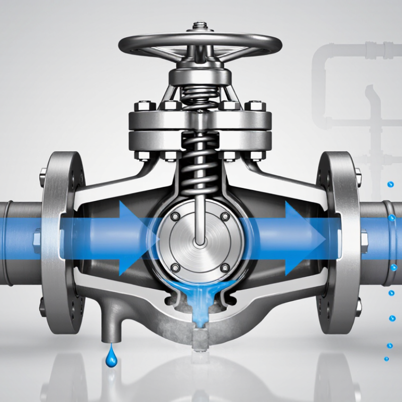
Inside the valve, a disc, ball, or piston responds to fluid pressure. Forward pressure opens the passage. Reverse pressure pushes the closing element onto its seat. The action needs no external power. In a chilled-water line, for example, the valve can stop heated water from moving backward when a pump shuts down. It is not a pressure regulator. It controls flow direction, not downstream pressure.

The U.S. Department of Energy reports that pumping systems may consume 25% to 50% of industrial electricity. Therefore, an incorrectly sized valve can create meaningful pressure loss and operating cost. A valve that is too small may increase turbulence, noise, and pump workload. A valve that is too large may close slowly and allow damaging reverse flow. The Hydraulic Institute also emphasizes checking system conditions, including flow rate, pressure, temperature, and fluid properties. Real installations are less tidy than diagrams. Even a good selection can perform poorly with debris or unstable flow.

Tips: Confirm the required flow rate and allowable pressure drop before selection. Check the valve’s orientation and inspect the seat during maintenance. A quiet valve is not always a healthy valve. Sudden closure may indicate water hammer risk.

Core Components and Internal Structure

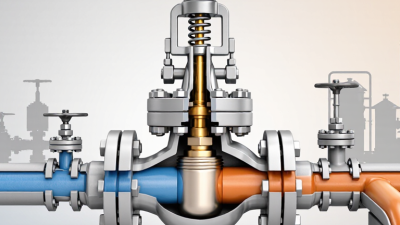
A flow check valve controls one-way fluid movement inside a pipe. Its body forms the pressure chamber and contains the moving parts. The inlet and outlet openings guide the fluid through the valve. Inside, a valve seat creates a precise sealing surface. A disc, poppet, or piston presses against this seat when reverse flow begins. Many designs also use a spring, guide, stem, and removable bonnet. Each component must align correctly. Small errors can cause leakage, noise, or unstable movement.

When upstream pressure rises, it pushes the closing element away from the seat. Fluid then passes through the open flow path. The guide keeps the disc centered and reduces contact with the body wall. If pressure falls, the spring or gravity moves the disc back toward the seat. Reverse pressure usually helps complete the closure. The seal then limits backflow. Fast closure is useful, but excessive speed may create water hammer. That risk is sometimes underestimated.

In field inspections, technicians often examine the seat, disc edge, spring, and sealing surfaces first. Rust particles or pipe scale can prevent full closure. A damaged guide may also make the disc wobble. The valve may appear normal from outside. Internal wear tells a different story. Flow direction arrows must match the actual installation. Incorrect positioning can defeat the valve’s purpose. Pressure ratings, temperature limits, and fluid compatibility require verification before operation. One practical weakness remains: a check valve cannot correct poor piping design. It only responds to changing pressure.

What Is a Flow Check Valve and How Does It Work? - Core Components and Internal Structure

Category Component or Feature Function and Operating Principle Typical Design Considerations
Purpose One-way flow control Allows fluid to move in the intended direction and automatically restricts reverse flow. The valve normally operates without an external actuator or manual control.
Main body Valve body Contains the internal flow passage, guides the moving closure member, and connects the valve to the piping system. The body material and wall thickness must suit the fluid, temperature, pressure, and connection standard.
Flow entrance Inlet port Receives the incoming fluid and directs it toward the closure member. The inlet should be installed according to the flow-direction arrow marked on the valve body.
Flow exit Outlet port Discharges fluid after the closure member has opened. Incorrect orientation can prevent opening or cause unwanted pressure loss.
Moving element Disc, poppet, ball, or piston Moves away from the seat when inlet pressure creates sufficient opening force, then returns toward the seat when flow decreases or reverses. The shape and mass affect pressure drop, response time, wear, and resistance to water hammer.
Sealing surface Valve seat Provides the stationary surface against which the closure member seals to stop reverse flow. Seat geometry, surface finish, and material compatibility influence leakage performance and service life.
Return mechanism Spring, when fitted Provides closing force so the valve can shut when the forward flow becomes too low or stops. Spring-loaded designs can close in various orientations; the spring rating affects cracking pressure and pressure loss.
Guidance Guide, stem, or cage Keeps the disc, poppet, or piston aligned with the seat during opening and closing. Proper alignment helps reduce uneven wear, vibration, and incomplete sealing.
Sealing support Gasket, O-ring, or body seal Seals the joint between body sections or around internal interfaces to prevent external leakage. Elastomer selection depends on chemical compatibility, temperature, and pressure conditions.
Opening condition Cracking pressure The minimum differential pressure required to begin moving the closure member away from the seat. The value depends on the valve design, spring force, closure weight, orientation, and fluid properties.
Forward-flow stage Valve open When inlet pressure exceeds outlet pressure by enough to overcome closing forces, the closure member lifts or swings open. Flow capacity is affected by the internal passage, valve size, closure travel, and pressure differential.
No-flow stage Valve closing As forward flow falls, the closure member moves toward the seat under gravity, spring force, or reverse-pressure force. A controlled closing action can help limit pressure surges and mechanical impact.
Reverse-flow stage Valve closed Reverse pressure pushes the closure member against the seat, restricting or stopping backflow. The actual leakage rate depends on the seat condition, fluid properties, pressure differential, and applicable test standard.
Common configurations Swing, lift, spring-loaded, and dual-plate Swing valves use a hinged disc; lift valves raise a guided closure; spring-loaded valves use a spring; dual-plate valves use two spring-assisted plates. Selection depends on flow direction, installation space, allowable pressure drop, closure speed, and maintenance requirements.
Key performance factors Pressure drop, leakage, and transient response A suitable valve permits the required forward flow while limiting reverse flow and avoiding excessive vibration or surge. Correct sizing, clean fluid passages, proper orientation, and compatibility with the piping system are essential for reliable operation.

How a Flow Check Valve Controls Fluid Movement

A flow check valve controls fluid movement by allowing flow in one direction and resisting reverse flow. It is commonly installed in water, air, oil, and process piping systems. Inside the body, a disc, ball, or piston responds to pressure changes. When inlet pressure rises above the valve’s cracking pressure, the internal part lifts from its seat. Fluid then passes through the opening.

When forward pressure drops, or outlet pressure becomes higher, the valve closes. A spring-loaded design closes quickly. A swing design may close more gradually. This action helps protect pumps, prevent backflow, and keep fluid from draining into unwanted areas. In field inspections, I have seen a poorly positioned valve cause noise, vibration, and unstable flow. The valve was functional, but the installation was not.

Tips:

Check the flow arrow before installation. It should match the intended movement. Confirm the valve’s pressure, temperature, and fluid compatibility. A valve that is too small can create excessive pressure loss. A valve with a high cracking pressure may restrict low-pressure systems. Keep the pipe clean, because grit can prevent the sealing surface from closing completely. Also inspect for water hammer after startup. It may indicate that the valve closes too sharply. Real systems are rarely perfect, so testing under normal operating conditions matters.

Main Types and Their Operating Differences

What Is a Flow Check Valve and How Does It Work?

A flow check valve permits fluid movement in one direction and blocks reverse flow. Its disc, ball, or diaphragm responds to pressure differences without external power. When inlet pressure exceeds outlet pressure, the valve opens. Reverse pressure pushes the closing element against its seat. Simple in theory.

Main Types and Their Operating Differences

Swing check valves use a hinged disc and suit steady, horizontal flow. They create relatively low pressure loss, but sudden closure can cause water hammer. Lift check valves move a piston or disc vertically. They offer reliable sealing under higher pressure, although their installation direction is less flexible. Wafer check valves are compact and lightweight. Their short travel helps reduce backflow, but poor alignment can damage the seat.

Ball check valves use a guided or free-moving ball. They perform well with dirty liquids, yet the ball may stick when deposits build up. Diaphragm check valves isolate the mechanism from the fluid. They are useful for corrosive or hygienic services, but diaphragm fatigue remains a concern. In field inspections, cracking pressure is often overlooked. That mistake can restrict pump startup.

Grand View Research valued the global industrial valves market at about USD 78 billion in 2023. The report also projects continued growth through 2030. The International Energy Agency expects global electricity demand to grow by more than 2% annually through 2026. These trends increase demand for dependable flow control. Still, selecting a valve from pressure data alone is imperfect. Temperature, fluid cleanliness, installation angle, and closing speed deserve equal attention.

What Is a Flow Check Valve and How Does It Work?

Typical cracking-pressure ranges by check-valve type

A flow check valve permits fluid to move in one direction and automatically prevents reverse flow. Swing and ball check valves generally use a hinged disc or ball, lift check valves use a guided piston or disc, and diaphragm check valves use a flexible diaphragm. Cracking pressure is the minimum upstream pressure difference needed to begin opening; actual values vary with valve size, fluid, temperature, and design.

Selection, Installation, and Maintenance Considerations

A flow check valve allows fluid to move in one direction and closes when reverse flow begins. Its disc, ball, or piston responds to pressure differences. This simple action protects pumps, prevents backflow, and reduces contamination risks. Selection requires more than matching pipe size. Check the fluid type, operating pressure, temperature, flow rate, and required cracking pressure. Consider water hammer, vertical piping, and frequent cycling. A valve with unsuitable materials may swell, corrode, or fail early. In practice, no selection is perfect without reviewing real operating conditions.

During installation, follow the flow arrow on the body. Keep the pipe interior clean. Even a small piece of debris can hold the valve open. Support nearby piping so the valve does not carry mechanical stress. Install it in the orientation recommended for its design, especially with spring-loaded or lift-style models. Leave enough access for inspection and removal. After installation, open the system gradually and check for leaks, vibration, and abnormal noise. A rushed pressure test can hide a weak connection.

Tips: Record the valve size, material, pressure rating, and installation date. Inspect sealing surfaces during scheduled maintenance. Look for reverse flow, pressure loss, rattling, or delayed closing. These signs need attention. Replace damaged seals and confirm that replacement parts match the service conditions. Do not assume a quiet valve is healthy; internal wear can develop without visible warning. Recheck the design when operating conditions change, because yesterday’s correct choice may become today’s restriction.