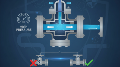
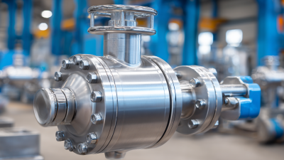
Why Is a Control Valve Used?
Why is a control valve used? In a process system, it adjusts the passage of fluid or gas to help maintain a desired operating condition. A sensor may detect falling pressure, rising temperature, or changing tank level. A controller then signals the valve actuator to open or close the valve by a measured amount. Small adjustments can matter. A few millimeters of stem movement may change flow, depending on the valve and process.
This role appears in many settings, from steam lines in factories to water circuits in commercial buildings. By regulating flow, a control valve can help equipment operate within specified limits and support consistent product quality. It may also reduce wasted energy when correctly selected and maintained. But it is not a cure-all. Poor sizing, incorrect installation, or a mismatched actuator can cause unstable control, noise, or excessive wear.
The sections that follow explain how control valves work, where they are used, and which factors guide selection. These include the fluid, pressure range, temperature, required flow capacity, and control signal. Safety requirements and maintenance access deserve attention too. The details vary by application. A valve that performs well on clean water may behave differently with steam or a fluid containing solids. The basic purpose is straightforward. Choosing the right one is not.
What a Control Valve Does in a Process Control Loop
Why Is a Control Valve Used?
What a Control Valve Does in a Process Control Loop
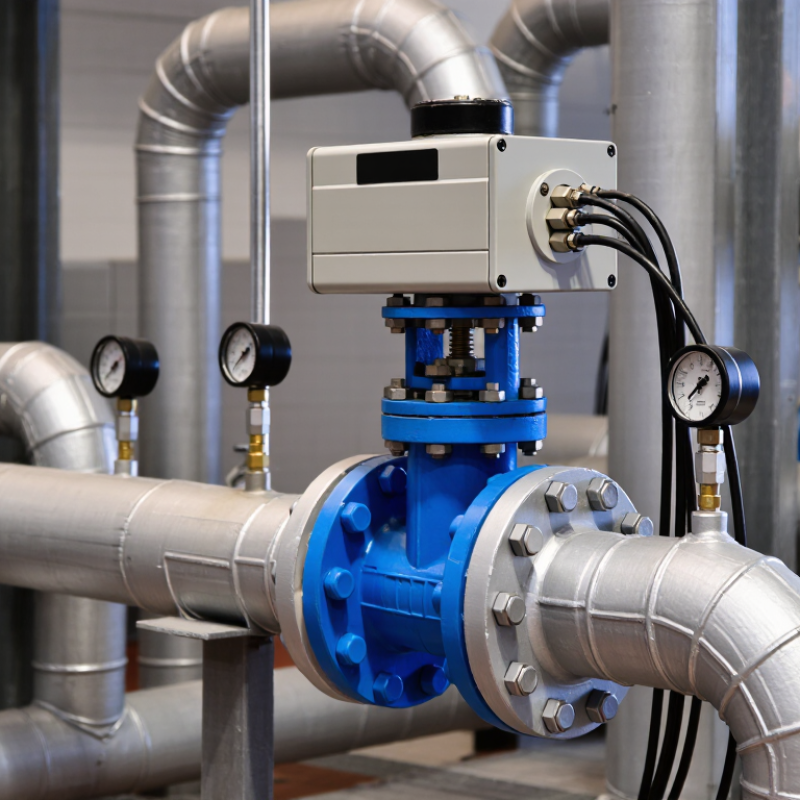
A control valve is the loop’s final control element: it adjusts how much fluid passes through a pipe. A sensor measures a process variable, such as temperature, pressure, or flow. The controller compares that reading with the target and sends a signal to the valve actuator. The actuator moves the valve plug or disc, changing the opening. Small movements can make a noticeable difference.
For example, if a tank’s temperature rises above its setpoint, the controller might signal a valve to admit more cooling water. As the temperature falls, the valve closes partway. This is feedback in action. The valve does not make the decision; it responds to the controller’s signal and helps correct the process.
In real systems, the response is rarely perfect. A valve that is oversized may make tiny adjustments difficult, while friction or wear can cause sluggish movement. That can lead to temperature swings or unstable flow. Engineers consider fluid properties, pressure drop, actuator response, and the valve’s failure position when selecting equipment. Operators also watch for hunting, leaks, or an actuator that fails to track its signal. Even a well-designed loop needs inspection.
Why Is a Control Valve Used?
A control valve adjusts process flow in response to a controller signal, helping keep a measured variable near its setpoint.
This illustrative equal-percentage valve characteristic shows normalized flow increasing as the valve opens. Actual flow depends on valve sizing, trim, and operating pressure conditions.
How 4–20 mA Signals Tell a Control Valve to Adjust
Why Is a Control Valve Used?
How 4–20 mA Signals Tell a Control Valve to Adjust
A control valve regulates the flow of liquid, gas, or steam through a pipe. It adjusts the opening to help maintain a target pressure, temperature, or flow rate. In a typical control loop, a sensor measures the process and sends its reading to a controller. The controller compares that reading with the target, then sends a 4–20 mA command to the valve’s positioner. Small signal. Big effect.
The signal represents a calibrated range: 4 mA usually corresponds to the lower command, and 20 mA to the upper command. For example, a rising temperature might prompt the controller to send a stronger signal, opening a cooling-water valve. The positioner checks the valve stem’s actual position and adjusts it to match the command. The relationship is not always “more current means more open”; valve action and configuration matter. A setup error can make a sensible signal produce the wrong response.
Tips: Confirm the configured signal range and valve action before troubleshooting. Use a meter to check the loop current, and compare it with the positioner’s displayed command. Also inspect tubing and wiring. They’re easy to overlook. A signal reading alone cannot prove that the valve is moving freely.
How Standard 3–15 psig Signals Drive Pneumatic Actuators
A control valve turns a controller’s pressure command into a physical change in flow. In the familiar 3–15 psig range, 3 psig is the calibrated lower endpoint, while 15 psig is the upper endpoint. That is a 12 psi span. NIST Special Publication 811 gives 1 psi as 6.894757 kPa, making the span about 82.7 kPa. The pressure change moves an actuator diaphragm, which shifts the valve stem against spring force.
At 3 psig, the valve may be near its calibrated starting travel; at 15 psig, near its endpoint. The exact response depends on the actuator and calibration. A positioner can help compensate for friction, linkage play, and changing process loads.
Small details matter. The signal’s direction and the valve’s response to air loss depend on actuator design, not just the pressure range. ISA-7.0.01 addresses instrument-air quality, since moisture and contaminants can affect pneumatic performance. A standard range helps make control predictable, but it cannot prevent calibration drift. That part still needs checking.
How IEC 60534 Uses Cv and Pressure Drop to Size Valves
A control valve is not sized by pipe diameter alone. Its job is to create a controllable pressure drop while passing the required flow. IEC 60534 provides sizing methods based on the valve’s flow coefficient and operating conditions. The coefficient may be expressed as Cv or, in metric units, Kv. Cv describes water flow in US gallons per minute at 60°F with a 1 psi pressure drop. Process fluids require adjustments for properties such as density and temperature. Small details matter.
For liquids, a basic relationship connects flow, pressure drop across the valve, and required capacity. More flow or less available pressure drop generally calls for a larger coefficient. But IEC 60534 considers more than this simple estimate. Liquid sizing checks vapor pressure, pressure recovery, and choking, where a further reduction in downstream pressure no longer increases flow. For gases and steam, changing density makes pressure ratio and compressibility important. The math is not magic.
Engineers commonly check minimum, normal, and maximum operating cases, then compare calculated capacity with the valve’s usable travel range. An oversized valve may hunt near its seat; an undersized one can restrict peak demand. For example, a water line with a large pressure drop at low flow may need different valve capacity than its pipe size suggests. Use reliable fluid data and pressure measurements. Plant conditions rarely stay perfectly steady, and that uncertainty deserves careful judgment rather than a guess.
Why Is a Control Valve Used? - How IEC 60534 Uses Cv and Pressure Drop to Size Valves
| Illustrative Service |
Flow Rate (Q) |
Specific Gravity (SG) |
Inlet Pressure |
Outlet Pressure |
Valve Pressure Drop (ΔP) |
Calculated Cv |
Equivalent Kv |
| Water flow control |
50 gpm |
1.00 |
100 psig |
75 psig |
25 psi |
10.0 |
8.65 |
| Light hydrocarbon liquid |
80 gpm |
0.70 |
90 psig |
74 psig |
16 psi |
16.7 |
14.5 |
| Glycol solution |
30 gpm |
1.10 |
80 psig |
71 psig |
9 psi |
10.5 |
9.08 |
| Higher-capacity water service |
120 gpm |
1.00 |
110 psig |
74 psig |
36 psi |
20.0 |
17.3 |
| Aqueous process solution |
65 gpm |
1.05 |
95 psig |
70 psig |
25 psi |
13.3 |
11.5 |
|
How to read the examples: For a preliminary turbulent-liquid estimate, Cv = Q × √(SG ÷ ΔP), with Q in US gallons per minute and ΔP in psi. Kv = 0.865 × Cv. The examples assume the stated pressure drop is across the valve and do not include piping corrections.
|
|
IEC 60534 sizing context: IEC 60534 provides standardized control-valve sizing methods; Kv is commonly used in metric calculations, while Cv is the corresponding customary-unit coefficient. Final sizing should account for the applicable fluid properties, valve and piping factors, operating range, and pressure-recovery or choked-flow limits. Gas, steam, flashing, and cavitating services require the appropriate IEC sizing equations rather than the simplified liquid estimate above.
|
Where Control Valves Regulate Flow, Pressure, Temperature, and Level
A control valve changes the rate of fluid moving through a pipe in response to a control signal. In a typical system, a sensor measures a process condition, a controller compares it with the target, and an actuator moves the valve. That matters. A valve that is too large may make small adjustments difficult, while a poorly selected valve can create excess noise or pressure loss.
For flow regulation, the valve can hold a steady rate despite changing demand. In pressure service, it can reduce upstream pressure or help maintain pressure downstream. Temperature control often depends on adjusting hot water, steam, or coolant flow through a heat exchanger. Small changes count. For level control, a valve may regulate liquid entering or leaving a tank, using level measurements to prevent overflow or an empty outlet.
The installation details matter too. Fluid properties, operating range, pipe layout, and actuator response all affect performance. A valve that behaves well at one operating point may be less stable at another. Engineers should check whether cavitation, flashing, or deposits could occur, and verify that the sensor is measuring the right location. In practice, tuning can require adjustment after startup; calculations alone do not capture every process fluctuation.